The ham radio HF antenna, of the half-wave dipole variety, requires a lot of horizontal space.
This Page Covers
1. “Full Sloper” Dipole
2. Inverted “V” Dipole
3. Inverted “U” Dipole
It’s possible, however, to “fit” a full-length half-wave dipole in less horizontal space, while retaining most, if not all the advantages of the “classic dipole” described elsewhere on this site. (See Antenna Section Contents in right hand column).
Below are some of the possible configurations. One of them actually has a slight performance edge for DX over the horizontal dipole!
The half-wave HF antennas described below do not impose the compromises of inductively “loaded” antennas (using coils) which are less efficient and have narrower useful bandwidth.
Warning!
High voltage is present at the ends of half-wave dipole antennas when transmitting.
The ends of the following antennas are lower above ground than normal!
Take all necessary precautions to prevent anyone from coming in contact with your antenna!
The Half-Wave
“Full Sloper” Dipole
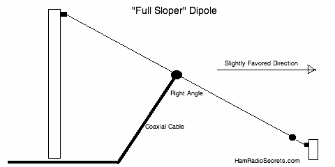
This ham radio HF antenna needs only one tall support and takes less horizontal space than if it were to be installed horizontally. 299Save
One end of the dipole is tied to the top of a tree (or other tall support). The other end slopes down at a convenient angle.
The radiation pattern will be almost omnidirectional … with a slight advantage toward the “sloping” direction.
The coaxial transmission line should be routed at a 90° angle from the “sloper” for at least 1/4 wavelength…
You will find more information on the many forms of slopers here.
- to avoid distortion in the radiation pattern…
- and to avoid RF from traveling back to the shack over the coax shield! (You can choke these unwanted RF currents with common mode RF chokes, as described here).
NOTE: Don’t have enough space for a full half-wave sloper on 160 or 80 meters?
Don’t give up! The inverted “V” or “U” configurations offer an excellent solution for restricted spaces.
The Inverted “V”
Dipole
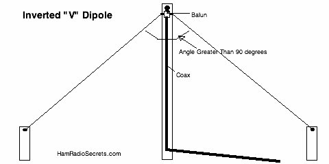
The inverted “V” dipole configuration is also a space saver! The angle between the two legs should be greater than 90° for best performance. 299Save
If you feed this antenna directly with a coax (without a balun at the antenna feed point), you will definitely need to insert two common mode RF chokes in the transmission line.
These are needed to “choke off” unwanted RF currents that will be induced by the radiating legs of the antenna, onto the transmission coaxial shield. (See bottom of this page for a link to more info).
The Inverted “U” Dipole
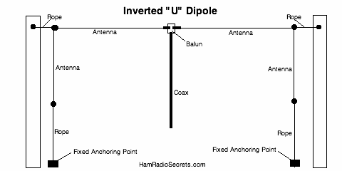
Most of the RF energy radiated and captured by a half-wave dipole antenna is concentrated in the middle 60% or so of the antenna. 299Save
The ends of the dipole can be “dropped” down from the horizontal, without much adverse effect.
Therefore, the dipole can be strung between two high supports, which can be separated by less than one half wavelength at the lowest operating frequency. (A dipole antenna can be operated on its odd multiple harmonics!)
The horizontal portion of this ham radio HF antenna should be at least 60% of the overall length, for best performance.
Common Mode
RF Chokes For The
Ham Radio HF Antenna
Common mode RF chokes are described in detail in another page of this site on the “classic” ham radio dipole.
The page on the “classic dipole” also…
- explains how to find the length of a dipole for a given frequency band,
- describes the hardware required to build a dipole.
NOTE: Don’t feel like making (winding) your own HF choke? A professionally made choke balun is the ideal solution.
Share this page: What’s this?
Found this page useful? Please pay it forward. Here’s how…
73 de VE2DPE
Claude Jollet
7, Rue de la Rive, Notre-Dame-des-Prairies, Québec, Canada J6E 1M9
QTH Locator: FN36gb

