
SummaryBlock diagramUsageConfigurationDownload & photo
BRIEFLY

A brief summary of this project
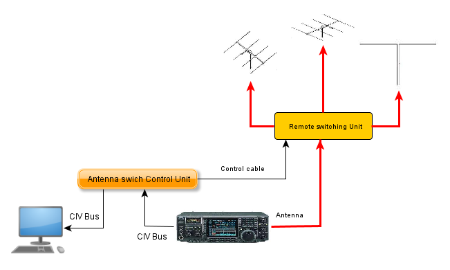
- The current working frequency is read form the radio using he Icom CI-V protocol.
- Antenna is switched when changing band, according to the configuration loaded within the control box.
- The device can be operated in automatic mode (switching based on frequency/band) as well as in manual mode (operator can select any antenna overwriting CAT informations).
- There are up to 7 antennas
- The device only works on ham radio band from 160 to 6 meters (this is a software limit that can be changed with few hacks in the code).
- Band to antenna association as well as antenna names can be simply changed using configurazion menu.
- No switching allowed during TX.
- Control box is optically isolated from the transceiver
- There is no need for a computer connected to the transceiver (in such config, the CI-V TRANSCEIVE option must be turned on).
- On the paper, the switch should also work with oldest ICOM radios provided that the radio is equipped with CI-V Protocol.
WHY I DID THIS
Since it’s quite difficult to cover all HF bands with a single antenna, many ham stations rely on different aerials (the classic config “triband and dipole”).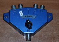
Anenna Switch
In past, I used to have at least 3 different HF antennas: the classic yagi for 10/15/20 meters, a dipole for WARC and finally “something” for 40 meters (I’m continously trying different setup for this band, due to space limitations). In my current station, I ended up having from 4 to 5 antennas to switch (just for HF, there are others for VHF…): so I faced the issue how to proprly switch all those antennas.
I started with the commonly used solution, so I bought a manual 4-way switch (I just replaced the PL connectors with N ones), but since it switches only 4 antennas, I quickly had to add a second switch (this time a remote unit I build myself). Of course, things worked but every band change was a challenge since I had to check both switches (sometimes finding myself asking “why I cannot hear anything?” and later discovering I selected the wrong one!).
In summer, 2011 I decided that it was time to automate also this task in my shack, using something able to switch the antenna based on the currently selected band on the radio. Of course, the issue was how to do it, since all commercial solutions I found wouldn’t fit all my needs (specially the first requirements, i.e. price!).
So I started writing down some requirements:
- Simple: as many of us, I don’t have lot of time to spend in radio, so the project should be both simple and quick to deploy. Based on my experience, large (ham) projects rarely end in a reasonable time frame (and sometimes they never end!)
- Manual/automatic mode: the contlo box should allow to select the proper antenna based on some configuration but should also allow the operator to select a different antenna than the one configured in the device (i.e. two antenna for the same band). Also it should be possible to operate in “indipendent mode” without requiring connections to radio/computer.
- Easy configuration: The device should be simple to configure.
FIRST TRIES
My first idea was to take advantage of one of the features of the marvellous logger32 (the software I’m using for logging), which allows to use a simple interface connected to the parallel port to switch several antennas (for more informations, see the Logger32 help file). This solution was nealy perfect for me, but I immediatly faced two issues: the first one (the simplest) was the circuit I need to deploy to both allow the “overwrite” feature as well as the “indipendent” working mode (i.e. switch the antenna even if the computer/logger32 are not available).
But the second challenge was nearly impossible to solve: the only parallel port in my computer is currently used by the rotor interface using ARS and there are no more PCI slot available inside for adding a PCI LPT port. Moreover, I noticed that modern computers lack the parallel port so with this solution my next computer would require at least 2 PCI parallel interface (one for ARS and the second for the antenna switch). And, before you ask, no, USB to LPT adapters cannot be used since they are specifically designed to drive printers and it’s almost impossible to drive single LPT pins with them.
I then remembered that ICOM has a BAND DECODER feature which basically sends a specific voltage on one of the accessessory pin based on the currently selected band on the radio. But again I immediatly stumbled upon a couple of issues: the first one was the same as before (I had to create an analog circuit to drive the switching, altough there are plenty of examples on the net); but it was the second one to be a real surprise: there is no voltage for any WARC bands, so any band decoder would miss 12,17 and 30 meters. When I read about this problem on the net, I cannot believe it so I tried on my IC756PRO and found it was sadly true. Probably ICOM engineers don’t like WARC bands!
THE IDEA
Since all simple solutions ended up in a “no go”, I started examining a way to grab the frequency information directly from the radio CAT feature using the CI-V port (already used to connect the radio to PC): altough this was even more difficult as before (the device should now be smart enought to understand the CI-V protocol), it seemed the best strategy which would indeed solve all my requirements. I also found (on the net) a similar device (I don’t recall the name right now) but was really too expensive. So I decided to better explore this way.
The firs part was the physical one, i.e. how to connect my “black box” to the radio since, as said before, the port was already being used to connect the radio to the computer: it was quite simple to accomplish this task due to the nature of the CI-V system. The CI-V protocol is a BUS based (2 wire) communication system allowing up to 4 radio and one controller (i.e. the computer) to share the same BUS line: since it’s not a point to point protocol, I could connect my device to the BUS and put it in “listening” mode to grab CI-V commands being sent from radio to computer and viceversa.
There are several Internet sites explaining in details how the CI-V protocol works, but let me to point out some of the features:
- CI-V is a standard serial communication data transfer using TTL levels: RXD and TXD channels are mixed together and sent to the single one-wire bus (in other words, it’s an half duplex system where a device can only send or receive at a time). CI-V interfaces are made using a simple MAX232 to translate TTL levels to RS232 values.
- Every device on the CI-V BUS has an address (specified in HEX format): each radio must be configured with an unique address within the bus while the controller, aka PC, always uses the standard address E0.
- I also noticed that every CAT software use to poll the radio every x milliseconds: a device on the bus can “listen” to this ask-answer protocol and “capture” the data.
- CI-V protocol also allows a “master” radio to drive several “slave devices” (example, a transceiver and an additional receiver) using the TRANSCEIVE option: when this option is set to ON, the master RTX send to the bus it’s frequency data whenever there is a change in the tuned frequency (it’s a sort of broadcast: the master tells to slaves which frequency/mode to tune). Of course, this works only when the radios cover the same frequencies, i.e. it’s not possible to tune an IC821 on 20 meters! This feature is really interesting since allows me to use the CI-V port even without a computer connection.
The second point was chose the proper “smart hardware” to decode CI-V data and store all configurable settings but again I had a simple answer: ARDUINO. I bought an ARUINO board some months before to build a multiple voltage/ampere meter for my lab power supply (this is a long standing project since I started it about 15 years ago! Every time i start working on it, I immediatly find a more interesting project!)
It was an hazard, because until then the only “program” I did with arduino was the simple “Led blinking”, a sort of “hello world”!